Trigonometry
| Category | Mathematics |
|---|
Overview
Matrices
A matrix is a rectangular array of real numbers.
The order of the matrix is the number of rows and columns.
For example, if the matrix has 3 rows and 2 columns, the order is 3 × 2.
Matrix Operations
Several operations are defined on matrices.
- Addition — The sum A + B of two matrices is obtained by adding the corresponding elements of A and B.
- Scalar multiplication — The multiplication of a matrix A by a real number k is the multiplication of every element of A by k.
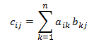
- Matrix multiplication — The multiplication of two matrices A and B with order (m × n) and (n × p) is a matrix with order (m × p) defined as:
Identify Matrix
An identity matrix is a square matrix that contains 1 for each element where the row number equals the column number, and zero for all other elements.
For example, here is the 3 × 3 identity matrix.

Vectors as Matrices
A 1 × n matrix is called a row vector.
A m × 1 matrix is called a column vector.
Coordinate System
The Cartesian plane has two perpendicular (orthogonal) axes (commonly labeled x and y).
Points are identified by specifying their extent along each axis.
The origin is identified as the point having coordinates (0, 0).
In a 3D space, we add an additional z axis.
Handedness
There are two varieties of Cartesian coordinate systems: left-handed and right-handed.
In both coordinate systems, the positive x-axis points to the right and the positive y-axis points up.
The handedness indicates which direction the positive z-axis points to.
Left-handed Coordinate System
In a left-handed coordinate system, the z-axis points away from the viewer, and rotations occur clockwise.
Right-handed Coordinate System
In a right-handed coordinate system, z-axis points towards the viewer, rotations occur counter-clockwise.
It's possible to convert the handedness by making two changes:
- Flip the order of the triangle vertices. For example, if the vertices are v0, v1, v2; they become v0, v2, v1.
- Scale the projection matrix by -1 in the z direction.
Coordinate Spaces
- World Space
- Model Space
- View Space (aka Projection Space, Camera Space, Eye Space)
- Clip Space
- Screen Space (aka Viewport Space, Window Space)
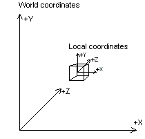
World Space
The coordinate system of the scene.
The center is arbitrary and determined by the world editor.
The model transforms are relative to the world space.
Model Space
The coordinate system of meshes.
The center of the mesh is determined by the DCC in which it was built.
The positions of the vertices of the mesh are relative to the center of the mesh.
The models in the scene are defined with a local transform and organized in a hierarchy.
Their world transform of a model is calculated by combining the local transforms with the parent models.
View Space
The coordinate system of the camera, or viewer.
The center is the eye of the camera.
Clip Space
The coordinate system of the screen is expressed in the clip space, which typically is in the range [-1, 1] for the x and y axis and [0, 1] for the z axis.
In OpenGL the z axis is also in the range [0, 1]. In Direct3D, the range of the z axia ca be customized but is typically left in the range [0, 1].
Space Transformations
World Transformation
The world transformation changes coordinates from model space, where vertices are defined relative to a model's local origin, to world space, where vertices are defined relative to an origin common to all the objects in a scene.
View Transformation
The view transformation locates the viewer in world space, transforming vertices into camera space.
In camera space, the camera, or viewer, is at the origin.
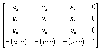
A common approach is to use the camera's world space position and a look-at point in the scene to derive vectors that describe the orientation of the camera space coordinate axes.
The camera position is subtracted from the look-at point to produce a vector for the camera's direction vector (vector n).
n = CameraPosition - LookAtPositionThen the cross product of the vector n and the y-axis of world space is taken and normalized to produce a right vector (vector u).
u = cross(n, UnitY)Next, the cross product of the vectors u and n is taken to determine an up vector (vector v).
v = cross(u, n)The right (u), up (v), and view-direction (n) vectors describe the orientation of the coordinate axes for camera space in terms of world space.
The x, y, and z translation factors are computed by taking the negative of the dot product between the camera position (c) and the u, v, and n vectors.
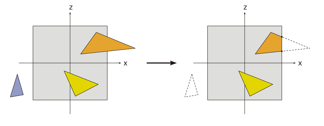
Projection Transformation
The projection transformation is typically a scale and perspective projection.
The projection transformation converts the viewing frustum into a cuboid shape.
Because the near end of the viewing frustum is smaller than the far end, this has the effect of expanding objects that are near to the camera.
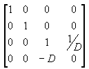
In The Viewing Frustum, the distance between the camera and the origin of the space defined by the viewing transformation is defined as D using 1/D.
The transformation puts the camera at the origin of the scene by translates it by -D in the z-direction using (0, 0, -D).
Multiplying these two transformations gives the following matrix.
Clip Space to Screen Space
The x, y, and z components of the vertices from the homogeneous clip space are divided by the w component to produce the normalized device coordinates.
The coordinates are scaled and biased to cover the entire viewport to produce coordinates in screen space.
Transformations
The most common transformations in computer graphics are translation, rotation, and scaling.
The rotation and scale transformations are linear transformations and can be represented as a 3x3 matrix.
However the translation transformation is an affine transformation and is expressed in a 4x4 matrix.
Therefore, a complete transformation is expressed as a 4x4 matrix.
To express a vector in 4D space, we add an additional coordinate w that is always equal to 1.
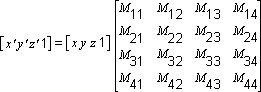
Any point can be transformed into another point by using a 4x4 matrix.
In the following example, a matrix is used to transform the point (x, y, z) into the new point (x', y', z').
Identity
An identity transformation maps every point onto itself. It's expressed by the identity matrix.
Translation
A translation transformation moves a point along an axis.
Translation matrix in 2D
Translation matrix in 3D
Rotation
A rotation transformation rotates a point around an axis of a specified angle.
Angles are in radians, and a positive angle is a counterclockwise rotation.
The rotation transformation is represented by different matrices for each axis.
Rotation Around the Origin
The matrix to rotate a point around the origin has the following form.
The transformed point is:
Rotation Around an Arbitrary Point
To rotate around a point other than the origin, the following matrix is used.
The transformed point is:
Rotations are always stored as a quaternion. A rotation matrix is computed from the quaternion.
Rotations can also be expressed as Euler angles.
- The order of the angles is important.
- Suffers from a problem called "gimbal lock".
Euler angles are used to compute a single rotation that is then stored as a quaternion.
Scale
A scale transformation scales a point up or down along each axis.
Scale matrix in 2D
Scale matrix in 3D
Skew (or Shear)
A skew transformation displaces a point in a fixed direction, by an amount proportional to its signed distance from a line that is parallel to that direction.
Skewing preserves the area of geometric figures and also the alignment and relative distances of colinear points.
The skew transform is defined by four parameters:
- Θ: The amount to skew along the x-axis, measured as an angle from the y-axis.
- Φ: The amount to skew along the y-axis, measured as an angle from the x-axis.
- (px, py): The x- and y-coordinates of the point about which the skew is performed.
The skew transform uses the following matrix.
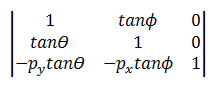
The transformed point is:
or equivalently:
Combined Transformations
We compose the translation, rotation and scale transformations into a 4x4 matrix.
Starting with an identity matrix, the top-left 3x3 matrix is the composition of the rotation and scale transformations and the last column is the translation vector.
Composition
The matrix multiplication is associative and we can therefore multiply transformation matrices together to obtain a composed transformation.
However, the matrix multiplication is not commutative and the order of the matrices is important.
In 3D graphics, scaling (S), rotation (R), and translation (T) result in a combined TRS transformation with each transformation applied right-to-left.
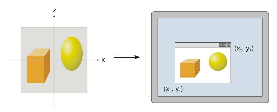
Projection
To represent a 3D space into a 2D space than can be displayed on a screen, we apply a projection transformation.
In 3D graphics, the most common projection is the perspective projection that creates the illusion of perspective.
In some cases, another common projection that is used is the orthogonal projection in which the perspective is flattened.
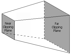
Perspective projection
A 3D scene is viewed from a virtual camera.
The area of the world that is visible through the virtual camera is called the view frustum which is a pyramid with the top cut off.
The clipping planes are the sides of the view frustum. They are determined by the field of view and the aspect ratio of the camera.
The projection transformation is expressed by a 4x4 matrix.
Perspective Divide
The perspective projection does not actually create the 3D effect. We need the perspective divide so that the further away something is, the more it will be pulled towards the center of the screen.
Each position is actually made of four components, X, Y, Z, and W with W initially always equal to 1.
Positions multiplied with the projection matrix have their W component increase the further away the object is.
The graphics rasterizer divides X, Y, Z by W. This division has the effect of scaling the z coordinate into the unit range [0, 1], which is needed for depth comparison.
Vertex Transformation
Point Transformation
The main responsibility of a vertex function is transforming positions from model space to clip space.
To transform a position from model space to clip space, multiple transformations are composed together:
- Model to view: from model space to camera space.
- View to projection: from camera space to clip space.
Typically, the composed matrix that represent the completed transformation is pre-calculated and referenced as the view model projection matrix.
MVP = Projection * View * Model
To transform a position, the vector is multiplied with the MPV matrix.
However, as position is a three dimensional vector, another component is added to build a four dimensional vector that can be multiplied by a 4x4 matrix.
The additional W component is set to 1 to conserve the translation.
Direction Transformation
Directions are transformed differently than points.
A typical case is the transformation of normals from model space to view space to perform lighting calculations.
If a direction is transformed with an MPV matrix, it will be translated and scaled which is incorrect for a direction.
The matrix needs to be transposed and then inverted.
MV = inverse(transpose((View * Model))
To transform a three dimensional direction (such as a normal), another component is added to allow a multiplication with a 4x4 matrix.
However, the W component is set to 0 to remove the translation from the operation.
Vertex Function
- Calculate the position of the object from the perspective of the camera
float4 position_model = float4(input_position, 1);
position_model = modelViewProjection_transform * position_model;- Calculate the normal from the perspective of the camera
float3 normal_model = float4(input_normal, 0);
normal_camera = (normalize(modelViewProjection_transform * normal_model.xyz);
Operations
Dot Product
The dot product is a function between two vectors, such that:
When the vectors are parallel
The dot product is equal to 1.
When the vectors are opposite directions
The dot product is equal to -1.
When the angle between the vectors is 90°
The dot product is equal to 0.
Hit-testing
Hit-testing is the operation that determine if a 3D mesh in the scene is hit by a 2D coordinate relative to the screen.
Transformations
The 2D coordinates are represented by a point.
The point is converted into a ray (unprojection) to perform intersection tests in world space.
There are several backward steps to move from screen space to world space.
- Screen Space to Clip Space
- Clip Space to View Space
- View Space to World Space
Screen space to clip space
- Unprojection: convert a point into a ray.
- Scale and bias the coordinates by the width and height of the viewport.
- Flip the Y axis to point up instead of down.
Clip Space to View Space
- Calculate the inverse of the projection transform.
- Apply the inverted matrix to the clip space coordinates.
- Set the direction of the ray forward (into the screen). In LH, Z is set to -Z to go in the +Z direction.
View Space to World Space
- The inverse of the view transform is the camera transform.
- Apply the camera transform to the ray direction to obtain the world direction of the ray.
- Set the origin of the ray as the camera position.
Bounding Volumes
3D models in the scene have associated bounding volumes that are simpler representations to perform efficient intersection tests.
There are different kind of shape that are typically used, and the intersection tests are implemented for each type.
- Bounding Sphere
- Axis-Aligned Bounding Box (AABB)
- Oriented Bounding Box (OBB)
Bounding Sphere
struct BoundingSphere
{
    float3 center;
    float radius;
}
Axis-Aligned Bounding Box
struct AABB
{
    float3 min;
    float3 max;
}
Intersection Tests
Ray-Sphere Intersection
References
- Math for Game Programmers: Interaction With 3D Geometry, GDC, https://www.youtube.com/watch?v=GpsKrAipXm8
- Linear Algebra for Graphics Programming, Metal by Example, http://metalbyexample.com/linear-algebra/
- Get Started with Win32 and C++ Module 3. Windows Graphics, Appendix: Matrix Transforms, https://docs.microsoft.com/en-us/windows/win32/learnwin32/appendix--matrix-transforms