Texture
| Tags | graphics |
|---|
Overview
To provide additional detail to the surface of meshes, textures are wrapped around objects.
The wrapping is defined by texture coordinates that are associated with each vertex of a mesh.
The texture coordinates are stored in video memory with the other vertex attributes.
In general, the fragment shader is sampling a color from a texture resources durning the lighting calculations.
Textures can also be used for special techniques (ie. displace select vertex positions).
Image
Textures contain image data.
The image data is stored in a specific pixel format.
The pixels are typically defined by 3 or 4 components.
- RGB: red, green, blue
- RGBA: red, green, blue and alpha.
Alpha typically defines the opacity of an image (no alpha is fully transparent and maximum alpha is fully opaque).
Images defined without an alpha component are fully opaque.
Image data is typically organized in a row-major order.
Typically, source images are stored in a 32-bit format where each component is represented using 8 bits values in the range [0, 255].
For HDR rendering, images can use a high precision format such as a floating point format where each component is represented using 32-bit values in the range [0, 1].
Colors are stored in the sRGB color space, and when a color is sampled in a fragment shader, it is converted to linear space before participating in the lighting calculations.
The final pixel color is converted back to the sRGB color space and is then presented to the display.
The texture image size is generally square and a power of two value.
Modern GPUs support arbitrary sizes, but the maximum number of texels is limited.
For example, DirectX 12 allows a maximum of 16384 x 16384 texels.
Texture Descriptor
When a texture object is created, it needs to be configured on the graphics device.
The properties include the texture’s type, size, pixel format, number of mipmap levels, sample count (for multisampling), and usage (read and/or write).
- Texture Type
- The dimension and arrangement of texture image data.
- single 1D, 2D or 3D image.
- multiple images arranged into an array or a cube.
- Pixel Format
- The size and bit layout of all pixels in the texture.
- Size
- Depending on the texture type: width, height and depth.
Pixel Format
A pixel format is the organization and characteristics of individual pixels in a texture (texels).
Graphic devices requires textures to be formatted with a specific pixel format.
The available pixel format varies on different platforms, so the source image data is typically converted offline into one of the supported pixel format on the target platform.
There are three varieties of pixel formats: ordinary, packed, and compressed.
A pixel format specifies:
- The order of components (such as R, RG, RGB, RGBA, BGRA).
- The data type for the component (such as float, signed int, unsigned int, normalized integer).
- Whether gamma compression and decompression is applied (srgb).
- For compressed formats, the compression method (such as ASTC, BC, EAC, ETC2, PVRTC).
Data Types
- float
- signed int (sint)
- unsigned int (uint)
- signed normal integer (snorm)
- Component values are in the range [-1.0, 1.0].
- unsigned normalized integer (unorm)
- Component values are in the range [0.0, 1.0].
Texture Coordinates
In a shader, the main task of the fragment function is to process incoming fragment data and calculate a color value for the final pixels. Therefore, the fragment function must be able to read each texel and output its color (sampling).
The relationship between a texture and geometric surface is defined by texture coordinates.
Texture coordinates are floating-point positions that map locations on a texture image to locations on a geometric surface.
In general, texture coordinates are in the range [0, 1].
Some effects require multiple set of texture coordinates.
Center
The coordinates at the center of a pixel are defined using truncating or rounding.
Projection
When a mesh is created in a content creation tool, the texture coordinates are defined in a 2D space (u, v). The texture coordinates are also known as UVs.
The texture coordinates are calculated using a projection function, or unwrapping algorithm.
The projection functions depend on the position of the vertices.
Common projections include spherical, cylindrical, and planar projection.
Some parametric curved surface already contain a natural set of values that can be used as texture coordinates.
- The spherical projection casts points onto an imaginary sphere centered around a specified point.
- The cylindrical projection computes the u-coordinate using a spherical projection, and computes the v-coordinate as the distance along the cylinder's axis.
- The planar projection uses an orthographic projection.
Addressing
In cases where the texture coordinates are out of the [0, 1] range, the addressing mode of the sampler determines which color will be sampled.
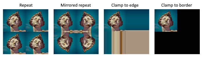
wrap
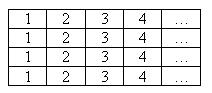
The image is repeated across the surface.
mirror
The image is repeated across the surface, but is also flipped on every other repetition.
clamp
Out of range values are clamped by repeating the edge of the image.
border
Out of range values are replaced by a specific border color.
1D Textures
1D textures are generally used as lookup tables, to convert color values sampled from a 2D texture to a different color.
3D Textures
Cube textures (or cube maps) are a special type of 3D texture.
Cube textures are a collection of six 2D textures that correspond to a direction along one of the axes of the 3D coordinate system.
Cube textures are typically unwrapped as a cross shape.
The texture coordinates are defined in a 3D space (u, v, w).
3D textures can be represented as a unit sphere, where each normal represent a direction that is used to sample a color at that location.
Sampling
Cube textures are sampled using three coordinates representing a direction.
The three coordinates are treated as a ray originating at the center of the cube, intersecting the face at a particular point on the cube.
Filtering
When the area being rendered to isn’t the same size as the texture, the sampler can use different algorithms to determine the color to sample.
These algorithms are called filtering modes.
- Magnification filter
- The sample is smaller than a pixel.
- Minification filter
- The sample is larger than a pixel.
- Mip filter
- To combine pixels between two mipmap levels.
The minification and magnification filters can be set to either:
- Nearest
- Selects the closest texel to represent the sampled point.
- Linear
- Selects four adjacent texels and produces a weighted average of them.
The mip map generation is performed in linear space, so it is important to convert the texture image from sRGB, perform the filtering in linear space, and convert it back to sRGB.
Anisotropic Texture Filtering
Anisotropy is the distortion visible in the texels of a 3D object whose surface is oriented at an angle with respect to the plane of the screen.
When a pixel from an anisotropic primitive is mapped to texels, its shape is distorted.
The anisotropy of a pixel is the elongation (length divided by width) of a screen pixel that is inverse-mapped into texture space.
Aliasing
Antialiasing is a technique that reduce the appearance of stair-step pixels when drawing any line that is not exactly horizontal or vertical.
This artifact is most noticable on the boundaries between polygons.
Antialiasing blends the pixels at the boundaries to produce a more natural look to the scene.
There are two antialiasing techniques: edge antialiasing and surface antialiasing.
Edge Antialiasing
Edge antialiasing works by adding an alpha edge to each polygon.
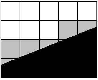
The polygon edge is black and the grey fragments are partially covered by the polygon edge.
The grey fragments are drawn with alpha blending and distinct levels of alpha transparency, as determined by how much of the polygon edge covered the fragment.
Antialiasing Filters
There are three basic types of antialiasing filters:
- Linear
- Gaussian
- Quincunx
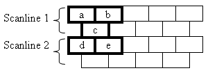
The scan lines look like:
Horizontal and Vertical Linear
The two linear filters are fairly straightforward.
result = (a + b) / 2Gaussian
The Gaussian filter works on nine pixels.
result = (a + 2×b + c + 2×d + 4×e + 2×f + g + 2×h + i) / 16Quincunx
result = (a + b + 4×c + d + e) / 8Screen-Based Antialiasing
The edge of triangles produce visible artifacts when the color is changing rapidly such as sharp shadow boundaries, or bright highlights.
Screen-based antialiasing improve the rendering quality of these cases.
The strategy of screen-based antialiasing is to use a sampling pattern for the screen and then weight and sum the samples to produce a pixel color.
Surface antialiasing is accomplished using either multisampling or supersampling.
Multisampling and Supersampling
Multisampling and supersampling require increasing the size of the back buffer, and scaling it back down using one of the multisample or supersample filters when it is copied to the front buffer.
A sample region consists of either two, four, or nine fragments in the frame buffer.
The z-value is computed separately for each fragment.
Supersampling
During polygon rasterization, the pixel shader inputs are computed once per fragment.
Full-Scene Antialiasing (FSAA) is also known as Supersampling Antialiasing (SSAA).
Multisampling
During polygon rasterization, the pixel shader inputs are computed once per sampling region.
Multisampling Antialiasing (MSAA) is faster than supersampling antialiasing, and more memory can be saved by decoupling sampling and coverage.
NVIDIA's Coverage Sampling AntiAliasing (CSAA) and AMD's Enhance Quality AntiAliasing (EQAA) store only the coverage for the fragment at a higher sampling rate.
Temporal Antialiasing
Temporal Antialiasing (TAA) technique use the result from previous frames to improve the image.
Usually, two to four frames are used.
Deferred shading techniques are not compatible with multisampling antialiasing, so temporal antialiasing is usually selected.
Morphological Antialiasing
Morphological antialiasing (MLAA) are post-processing techniques that attempt to detect edges.
The two most popular open-source techniques are Fast Approximate Antialiasing (FXAA) and Subpixel morphological Antialiasing (SMAA).
Mip Maps
When filtering a texture, the effect of under-sampling produces a shimmering artifact (aliasing).
Mipmapping is a technique devised to solve this problem.
The term mip is based on the Latin phrase multum in parvo, meaning "much in a small space".
Mipmaps are a sequence of prefiltered textures (levels).
Each mipmap is a factor of two smaller than its predecessor.
The combination of minification, magnification and mip filters produces different results.
Generation
The creation of mipmaps involves creating smaller and smaller versions of the original texture, until a level has a dimension that is only one pixel in size.
The number of mipmap levels is determined by the formula:
floor(log2(max(width, height)) + 1
For example, a 512×256 texture has 10 levels.
Blending
To make an object appear transparent, it is rendered with an alpha component of less than 1.0.
Blending the fragment's color with the pixel's color of the scene is known as blending.
Over
The most common blending effect is the over operator.
A portion of the source and destination colors are added together.
When using premultiplied alpha values, the blending is more efficient.
It is better to use premultiplied alpha values when blending and filtering is performed.
When performing filtering with non-premultiplied alpha values, artifacts around the edges of objects can appear.
Under
The over operator requires drawing from back to front to produce the correct results.
An alternative is the under operator.
Additive
Additive blending is used for glowing effects such as lightning or sparks.
Instead of attenuating the destination pixels, they are brightened.
Aliases
2D games have a large number of 2D textures (sprites).
A traditional approach to reduce the number of render state changes is to build a sprite sheet.
A sprite sheet contains smaller images composited into a single texture.
There are several problems with atlases:
- They require padding because of filtering.
- Repeat and mirror modes do not work.
- Automatic generation of mip maps will produce incorrect results.
Modern graphics APIs support texture arrays.
Texture arrays also reduce number of render state changes, and provide a solution to the issues encountered with texture atlases.
Compression
The traditional image compression algorithms such as JPEG or PNG are not efficient when decoded on the GPU.
Therefore, new compression algorithms have been developed.
The most common are S3TC, PVRTC, ETC, and ASTC.
There are loss-less and lossy compression formats.
- A loss-less format preserves the image contents.
- A lossy format trades a reduction in image quality for smaller memory usage.
Texture are generally compressed offline on the CPU.
In some cases, dynamic textures are compressed on the GPU.
S3TC
S3 Texture Compression (S3TC)
Also known as DXT in DirectX and Block Compression (BC) in DirectX 10+.
Developed by S3 Graphics.
- Supported by DirectX 6.0 in 1998.
- Supported by OpenGL 1.3 in 2001.
- Not supported on mobile hardware.
Block-based texture format.
Codecs:
- DXT1
- DXT2/3
- DXT4/5
- DXTn
DXT1
DXT1 (BC1) is for textures that are opaque or have a single transparent color.
Converts 16 texels into 64-bit blocks, consisting of two 16-bit RGB 5:6:5 color values (or 1-bit alpha block) and a 4x4 bitmap as a 2-bit lookup table.
DXT2 and DXT3
DXT2 and DXT3 (BC2) are for textures where the alpha channel is explicit.
DXT2 textures have a premultiplied alpha channel.
Converts 16 texels into 128-bit blocks, consisting of 64 bits of alpha channel data (4-bits for each pixel) followed by 64 bits of color data (DXT1).
DXT4 and DXT5
DXT4 and DXT5 (BC3) are for textures where the alpha channel is interpolated.
DXT4 textures have a premultiplied alpha channel.
Converts 16 texels into 128-bit blocks, consisting of 64 bits of alpha channel data (two 8-bit alpha values and a 4x4 bitmap as a 3-bit lookup table) followed by 64 bits of color data (DXT1).
DXTn
DXTn supports 3D compressed textures.
The texture is divided up into blocks that are only affected by depth and not width or height.
They are one of the following four sizes:
- 4 x 4 x 1 (depth is 1)
- 4 x 4 x 2 (depth is 2)
- 4 x 4 x 3 (depth is 3)
- 4 x 4 x 4 (depth is 4 or higher)
BC4
One channel, encoded as alpha in BC3.
BC5
Two channels, each encoded as alpha in BC3.
BC6H
BC6H is for high dynamic range (HDR) textures with RGB components.
Each texel has a 16-bit floating point per component.
BC6H is known as BPTC_FLOAT in OpenGL.
BC7
BC7 is for low dynamic range (LDR) textures with RGBA components.
BC6H is known as BPTC in OpenGL.
PVRTC
PowerVR Texture Compression (PVRTC)
Developed by Imagination Technologies in 2003.
Operates by downsampling the source image into two smaller images, which are upscaled and blended to reconstruct an approximation of the original.
PVRTC is the preferred format when targeting A7 processors.
ETC
Ericsson Texture Compression (ETC)
Developed by Ericsson in 2005.
Block-based texture format.
Codecs:
- ETC1
- Supported in OpenGL ES.
- Does not support alpha components.
- ETC2
- Supported in OpenGL ES 3.0.
- Expands ETC1 to provide higher quality compression.
- Supports alpha components.
- EAC
- Based on ETC1 and ETC2.
- Used for one or two channel data.
ASTC
Advanced Scalable Texture Compression (ASTC)
Developed by AMD in 2012.
Block-based texture format.
Incorporates a selectable block size.
ASTC offers the best quality-to-size ratio on hardware where it is available.
ASTC can handle both LDR and HDR textures.
Formats
PVR
A PVR file can contain uncompressed data or compressed data in several formats including S3TC, ETC, and PVRTC.
PVR2
struct PVR_Texture_Header
{
	PVRTuint32 dwHeaderSize;
	PVRTuint32 dwHeight;
	PVRTuint32 dwWidth;
	PVRTuint32 dwMipMapCount;
	PVRTuint32 dwpfFlags;
	PVRTuint32 dwTextureDataSize;
	PVRTuint32 dwBitCount;
	PVRTuint32 dwRBitMask;
	PVRTuint32 dwGBitMask;
	PVRTuint32 dwBBitMask;
	PVRTuint32 dwAlphaBitMask;
	PVRTuint32 dwPVR;
	PVRTuint32 dwNumSurfs;
};
PVR3
struct PVRTextureHeaderV3
{
	PVRTuint32	u32Version;
	PVRTuint32	u32Flags;
	PVRTuint64	u64PixelFormat;
	PVRTuint32	u32ColourSpace;
	PVRTuint32	u32ChannelType;
	PVRTuint32	u32Height;
	PVRTuint32	u32Width;
	PVRTuint32	u32Depth;
	PVRTuint32	u32NumSurfaces;
	PVRTuint32	u32NumFaces;
	PVRTuint32	u32MIPMapCount;
	PVRTuint32	u32MetaDataSize;
};
ASTC
#define MAGIC_FILE_CONSTANT 0x5CA1AB13

struct astc_header
{
	uint8_t magic[4];
	uint8_t blockdim_x;
	uint8_t blockdim_y;
	uint8_t blockdim_z;
	uint8_t xsize[3];
	uint8_t ysize[3];
	uint8_t zsize[3];
};
Texture Effects
Bump Mapping
Details that would be too complicated to render using triangles can be rendered using a bump mapping technique.
Bump mapping gives a 3D appearance using texture mapping, without additional geometry.
The principle of bump mapping is to apply a perturbation to the base geometry in a fragment shader.
The perturbation is stored in a texture called bump texture.
Instead of modifying the vertices, the perturbation is applied to the vertex normals when performing the lighting calculation.
The direction of the normal is changed in tangent space.
The axis of the tangent space are defined by the tangent and bitangent vectors, that are stored with the vertices.
We perform the lighting calculations relative to the normal map in object space.
The matrix that represent the tangent space is known as the TBN matrix.
The light direction is transformed by the TBN matrix from world space to tangent space.
Normal Mapping
An alternative to bump mapping, is to use a normal map texture.
A normal map is a texture that encodes the normal in tangent space (x, y, z) mapped to [-1, 1].
For example, using an 8-bit texture, 0 is mapped to -1 and 255 is mapped to 1.
The red channel is the x deviation, the green channel is the y deviation, and the blue channel is the z deviation.
For each fragment, we sample the normal from the normal map and use it directly in the lighting calculation.
Parallax Mapping
Parallax mapping improves the effect by taking into account the view angle.
The bumps appear to have a height, shift location depending on the view angle, and can block each other.
The bumps are stored in a height map texture.
For each fragment, we sample the height from the height map.
The height is scaled and biased and used with the view angle in tangent space to offset the texture coordinates.
The scale determines how high is the height map, and the bias determines the height at which no offset occurs.
Parallax Occlusion Mapping
Decals
A decal is an image that is applied on top of another surface.
Decals have a transparent background, that is determined with texels that have an alpha of 0.
Cutouts
A silhouette can be rendered by using an image with a transparent background to discard some fragments on a rectangular surface.
These cutouts can be rendered as billboards, to ensure that they always face the camera.
However, for cutouts that face the camera in a 2D plane, the illusion breaks down when the camera is above ground level.
Textured Lights
Projective textures can be used to modulate the light intensity.
Procedural Textures
Noise Textures
A noise texture is generated through a node function.
A noise function is generally sampled at successive power-of-two frequencies called octaves.
Each octave has a weight, and the sum of the weighted samples is called a turbulence function.
Perlin is a common method for sampling a noise function.
Cellular Textures
A cellular texture is generated by measuring the distances from each locations to a set of feature points scattered through space.
Animation
Textures can be animated using two methods.
Dynamic Image
A dynamic texture image changes from frame to frame.
A common example of a dynamic image, is a texture that displays a video source such as a media resource or a webcam feed.
Dynamic Coordinates
The modification of the texture coordinates from frame to frame can also produce animation.
A common method to modify the texture coordinates is to perform a transformation with a texture matrix in a shader program.
Many effects can be produced such as offsets, rotation, zoom, shearing, image warping and morphing...